INTRODUCTION TO COMBINATIONAL LOGIC CIRCUITS!
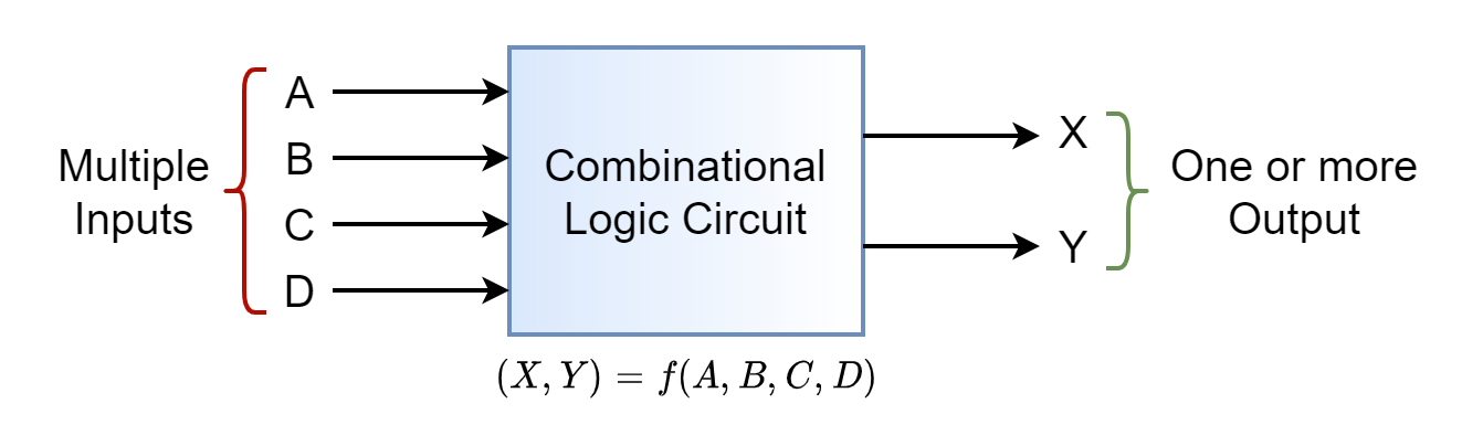
Combinational circuits are very well known components in digital electronics which can provide output instantly based on the current input. Unlike sequential circuits, a combinational circuit listens for input signal and and generates output no matter what is the past input or state as it has no feedback or memory component.
0
51

- A combinational circuit, also called a combinational logic circuit, is a digital electronic circuit whose output is determined by present inputs only.
- In other words, a combinational circuit is a digital logic circuit whose output depends only on the present input values and does not depend on any feedback or previous input or output values.
- The most important characteristic of a combinational circuit is that it does not have any feedback path between input and output. Therefore, the combinational circuits can be categorized as open-loop systems.
TYPES OF COMBINATIONAL LOGIC CIRCUITS:
HALF ADDER
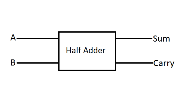
- It is a arithmetic combinational logic circuit designed to perform addition of two single bits.
- The half adder adds two binary digits called as augend and addend and produces two outputs as sum and carry; XOR is applied to both inputs to produce sum and AND gate is applied to both inputs to produce carry.
- The half adder can add only two input bits (A and B) and has nothing to do with the carry if there is any in the input. So if the input to a half adder have a carry, then it will neglect it and adds only the A and B bits. That means the binary addition process is not complete and that's why it is called a half adder.

FULL ADDER

- To overcome the above limitation faced with Half adders, Full Adders are implemented. It is a arithmetic combinational logic circuit that performs addition of three single bits.
- The first two inputs are A and B and the third input is an input carry as C-IN.

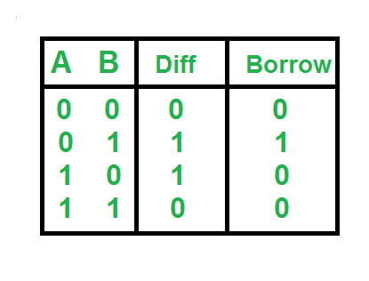
HALF SUBTRACTOR
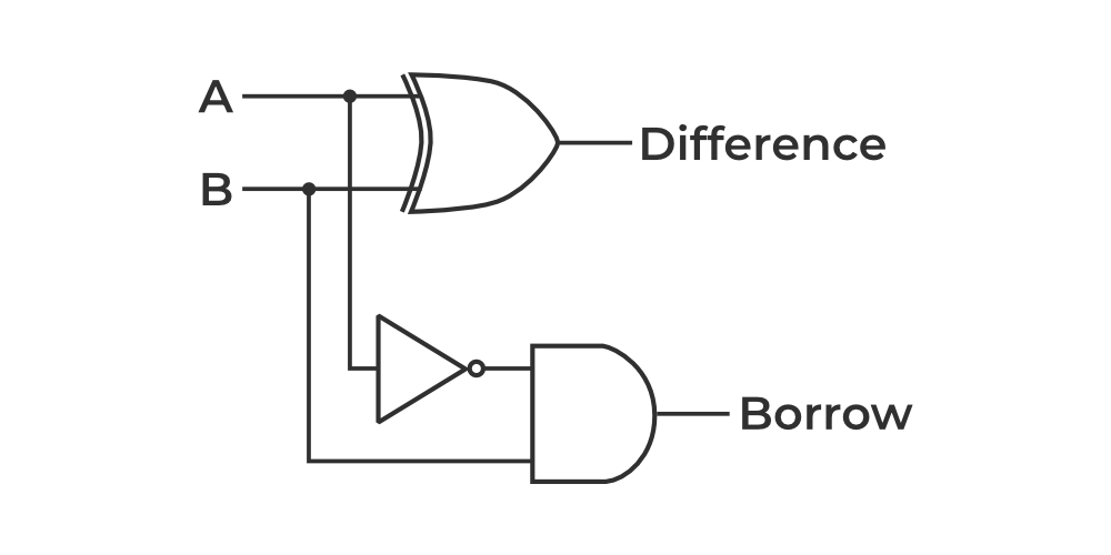
- It is a combinational logic circuit designed to perform the subtraction of two single bits.
- It contains two inputs (A and B) and produces two outputs (Difference and Borrow-output).
- The half subtractor boolean expressions are :
• D = (A’B + AB’) = A ⊕ B
• Bout = A’B
FULL SUBTRACTOR

- A full subtractor is a combinational circuit that performs a subtraction between two bits, taking into account that a 1 may have been borrowed by a lower significant bit. The circuit has three inputs and two outputs.
- Input variables are minuend (A), subtrahend (B), and previous borrow (Bin); output variables are difference (D) and output borrow (Bout).
MULTIPLEXER
- A multiplexer is a combinational circuit that has many data inputs and a single output, depending on control or select inputs.
- For N input lines, log2(N) selection lines are required, or equivalently, for input lines, n selection lines are needed.
- Multiplexers are also known as “N-to-1 selectors,” parallel-to-serial converters, many-to-one circuits, and universal logic circuits. They are mainly used to increase the amount of data that can be sent over a network within a certain amount of time and bandwidth.
-
The Multiplexer are mainly of two types-
- 2×1 Mux
- 4×1 Mux
2×1 Multiplexer
- The 2×1 is a fundamental circuit which is also known 2-to-1 multiplexer that are used to choose one signal from two inputs and transmits it to the output. The 2×1 mux has two input lines, one output line, and a single selection line.
- It has various applications in digital systems such as in microprocessor it is used to select between two different data sources or between two different instructions.
-
The output of the 2×1 Mux will depend on the selection line S0,
- When S is 0(low), the I0 is selected
- when S0 is 1(High), I1 is selected
-
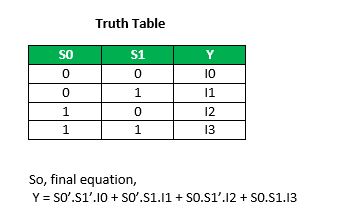
Using the Truth Table ,the Logical Expression for Mux can be determined as

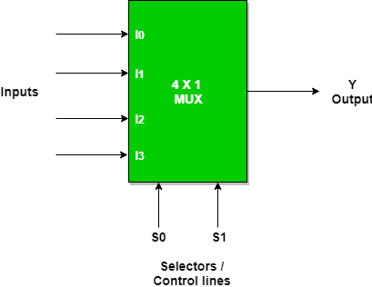
4×1 Multiplexer
- The 4×1 Multiplexer which is also known as the 4-to-1 multiplexer. It is a multiplexer that has 4 inputs and a single output.
- The Output is selected as one of the 4 inputs which is based on the selection inputs. The number of the Selection lines will depend on the number of the input which is determined by the equation ,In 4×1 Mux the selection lines can be determined as ,slo two selections are needed.
-
The output of the multiplexer is determined by the binary value of the selection lines
- When S1S0=00, the input I0 is selected.
- When S1S0=01, the input I1 is selected.
- When S1S0=10, the input I2 is selected.
- When S1S0=11, the input I3 is selected.
DEMULTIPLEXER
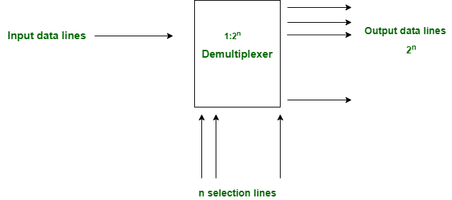
- DEMUX or De-Multiplexer is a data distributor combinational circuit. It works in a reverse way of the Multiplexer.
- The DEMUX has 1 input port and 2^n output lines. Here n signifies the selection line for a DEMUX. As per the selection line value, the DEMUX input lines will be connected to receive the output. Demultiplexer receives digital information from a single source and converts it into several sources.
- It takes input from one source and also converts the data to transmit towards various sources. The demultiplexer has one data input line. The demultiplexer has several control lines (also known as select lines). These lines determine to which output the input data should be sent. The number of control lines determines the number of output lines.
- A 1x4 DEMUX has only one input which is denoted as I. There are two selection lines i.e. S1 and S0. At last, the DEMUX has output lines including Y3, Y2, Y1 &Y0. Here is the 1x4 DEMUX with diagram as mentioned below:

-
The truth table of 1x4 DEMUX is given below:
Selection Inputs Outputs S1 S0 Y3 Y2 Y1 Y0 0 0 0 0 0 I 0 1 0 0 I 0 1 0 0 I 0 0 1 1 I 0 0 0
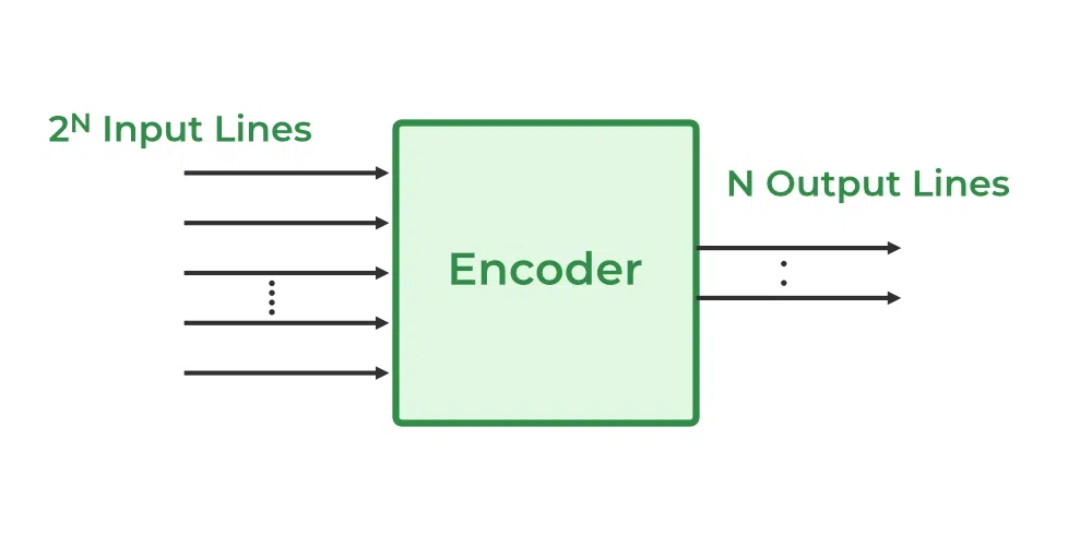
ENCODER
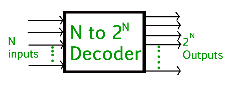
- An encoder is a combinational circuit that converts binary information in the form of a 2N input lines into N output lines, which represent N bit code for the input.
- For simple encoders, it is assumed that only one input line is active at a time.
- The basic principle of an encoder is to assign a unique binary code to each possible input. For example, a 2-to-4 line encoder has 2 input lines and 4 output lines and assigns a unique 4-bit binary code to each of the 2^2 = 4 possible input combinations.
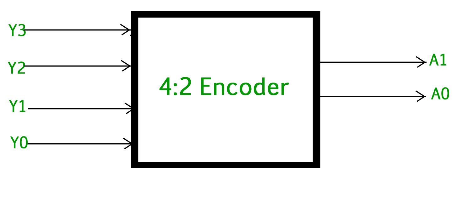
- The 4 to 2 Encoder consists of four inputs Y3, Y2, Y1 & Y0, and two outputs A1 & A0. At any time, only one of these 4 inputs can be ‘1’ in order to get the respective binary code at the output.
- The figure below shows the logic symbol of the 4 to 2 encoder:
-
The Truth table of 4 to 2 encoders is as follows:
INPUTS OUTPUTS Y3 Y2 Y1 Y0 A1 A0 0 0 0 1 0 0 0 0 1 0 0 1 0 1 0 0 1 0 1 0 0 0 1 1
- A1 = Y3 + Y2
- A0 = Y3 + Y1
DECODER
- A binary decoder is a digital circuit that converts a binary code into a set of outputs. The binary code represents the position of the desired output and is used to select the specific output that is active.
- The basic principle of a binary decoder is to assign a unique output to each possible binary code. For example, a binary decoder with 4 inputs and 2^4 = 16 outputs can assign a unique output to each of the 16 possible 4-bit binary codes.
- The inputs of a binary decoder are usually active low, meaning that only one input is active (low) at any given time, and the remaining inputs are inactive (high). The active low input is used to select the specific output that is active.
- The 2 binary inputs labeled A and B are decoded into one of 4 outputs, hence the description of a 2-to-4 binary decoder. Each output represents one of the minterms of the 2 input variables.

- The output values will be: Qo=A’B’ Q1=A’B Q2=AB’ Q3=AB The binary inputs A and B determine which output line from Q0 to Q3 is “HIGH” at logic level “1” while the remaining outputs are held “LOW” at logic “0” so only one output can be active (HIGH) at any one time.
- Therefore, whichever output line is “HIGH” identifies the binary code present at the input, in other words, it “decodes” the binary input.