INRODUCTION TO SEQUENTIAL LOGIC CIRCUITS!
Sequential circuits are digital circuits that store and use the previous state information to determine their next state. Unlike combinational circuits, which only depend on the current input values to produce outputs, sequential circuits depend on both the current inputs and the previous state stored in memory elements.
0
40
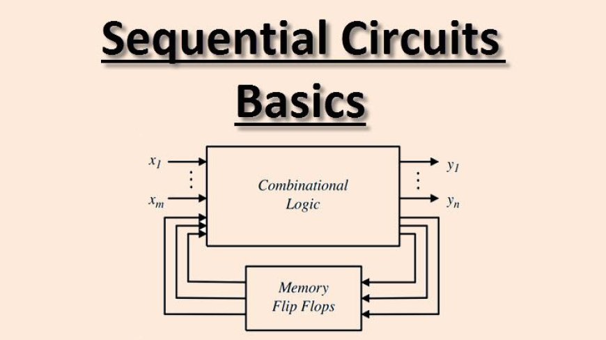
- Sequential circuits are digital circuits that store and use previous state information to determine their next state.
- They are commonly used in digital systems to implement state machines, timers, counters, and memory elements and are essential components in digital systems design.
- The memory elements in sequential circuits can be implemented using flip-flops, which are circuits that store binary values and maintain their state even when the inputs change.
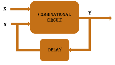
- A combinational circuit produces an output based on input variables only, but a sequential circuit produces an output based on current input and previous output variables.
- There are two types of sequential circuits:
SYNCHRONOUS SEQUENTIAL CIRCUIT
- These circuits uses clock signal and level inputs (or pulsed) (with restrictions on pulse width and circuit propagation).
- The output pulse is the same duration as the clock pulse for the clocked sequential circuits.
- Since they wait for the next clock pulse to arrive to perform the next operation, so these circuits are bit slower compared to asynchronous. Level output changes state at the start of an input pulse and remains in that until the next input or clock pulse.

ASYNCHRONOUS SEQUENTIAL CIRCUIT
- An asynchronous sequential circuit does not have the clock signal; the transitions between different states occur due to the ‘change of inputs’.
- This makes them suitable for applications which involve low power input or when a clock signal may not be needed.
- Asynchronous sequential also known as self-timed or ripple-clock circuits, are digital circuits that do not use a clock signal to determine the timing of their operations. Instead, the state of the circuit changes in response to changes in the inputs.
- In an asynchronous sequential circuit, each flip-flop has a different set of inputs and outputs, and the state of the circuit is determined by the outputs of the flip-flops. The state transition function, which is a Boolean function that describes the behavior of the circuit, determines the next state of the circuit based on the current inputs and the previous state stored in the flip-flops.
FLIP - FLOPS
- A flip flop is a sequential circuit which consist of single binary state of information or data. The digital circuit is a flip flop which has two outputs and are of opposite states.
- The flip-flop is a circuit that maintains a state until directed by input to change the state. A basic flip-flop can be constructed using four-NAND or four-NOR gates.
- Flip-flop is popularly known as the basic digital memory circuit. It has its two states as logic 1(High) and logic 0(low) states.
TYPES OF FLIP-FLOPS
- SR Flip Flop
- JK Flip Flop
- D Flip Flop
- T Flip Flop
SR FLIP-FLOP
- In the flip flop, with the help of preset and clear when the power is switched ON, the states of the circuit keeps on changing, that is it is uncertain.
- It may come to set(Q=1) or reset(Q’=0) state. In many applications, it is desired to initially set or reset the flip flop that is the initial state of the flip flop that needs to be assigned.

-
Characteristics Equation for SR Flip Flop:
QN+1 = QNR’ + SR’
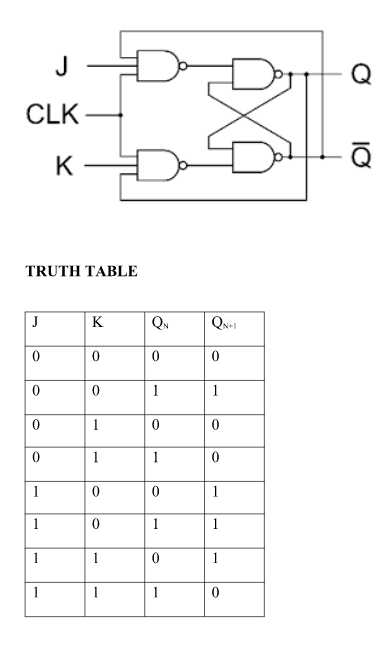
JK FLIP-FLOP

- JK flip-flops are very similar to SR flip-flops. The J input is just like the S input in that when asserted, it sets the flip-flop. Similarly, the K input is like the R input where it clears the flip-flop when asserted.
- The only difference is when both inputs are asserted. For the SR flip-flop, the next state is undefined, whereas, for the JK flip-flop, the next state is the inverse of the current state. In other words, the JK flipflop toggles its state when both inputs are asserted.
-
Given Below is the Operations of J-K Flip Flop:
- Case 1 (PR=CLR=0 ):This condition is in its invalid state.
- Case 2 (PR=0 and CLR=1):The PR is activated which means the output in the Q is set to 1. Therefore, the flip flop is in the set state.
- Case 3 (PR=1 and CLR=0):The CLR is activated which means the output in the Q’ is set to 1. Therefore, the flip flop is in the reset state.
- Case 4 (PR=CLR=1):In this condition the flip flop works in its normal way whereas the PR and CLR gets deactivated.
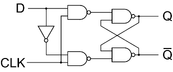
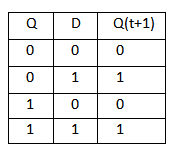
D FLIP-FLOP

- Delay or D flip-flop is a better alternative that is very popular with digital electronics. They are commonly used for counters, shift registers, and input synchronization.
- In the D flip-flops, the output can only be changed at the clock edge, and if the input changes at other times, the output will be unaffected.
-
Given Below is the operation of D Flip-Flip:
- Case 1 (PR=CLR=0):This conditions is represents as invalid state where both PR(present) and CLR(clear) inputs are inactive.
- Case 2 (PR=0 and CLR=1):This state is set state in which PR is inactive (0) and CLR is active(1) and the output Q is set to 1.
- Case 3 (PR=1 and CLR=0):This state is reset state in which PR is active (1) and CLR is inactive (0) and the complementary output Q’ is set to 1.
- Case 4 (PR=CLR=1):In This state the flip flop behaves as normal, both PR and CLR inputs are active(1).
-
Characteristics Equation for D Flip Flop:
QN+1 = D
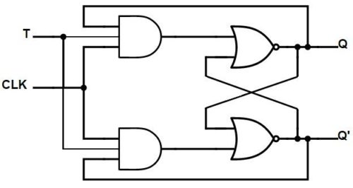
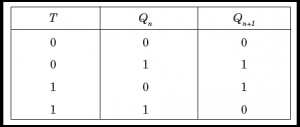
T FLIP-FLOP
- A T flip-flop is like a JK flip-flop. These are single-input versions of JK flip-flops. This modified form of the JK is obtained by connecting inputs J and K together. It has only one input along with the clock input.
-
Given Below is the Operation of T Flip-Flop:
- Case 1 (T=0):In this condition the flip-flop remains in its current state regardless of clock input,Also the Output Q will remain unchanged unit the value of T will not change.
- Case 2 (T=1):In this condition the flip flop will change when T input is 1,At each rising or falling edge of the clock signal the output Q will be in complementary state.
-
Characteristics Equation for T Flip Flop:
QN+1 = Q’NT + QNT’ = QN XOR T